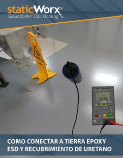
Identifying a Proper Path to Ground
Several acceptable methods are used to ground static control flooring depending on local codes, the job conditions, and the personal preference of the contractor. The three most widely used paths to ground are:
AC WALL OUTLET
(circuit ground – most common,
shown in example below)

GROUNDING ROD
(natural earth ground)
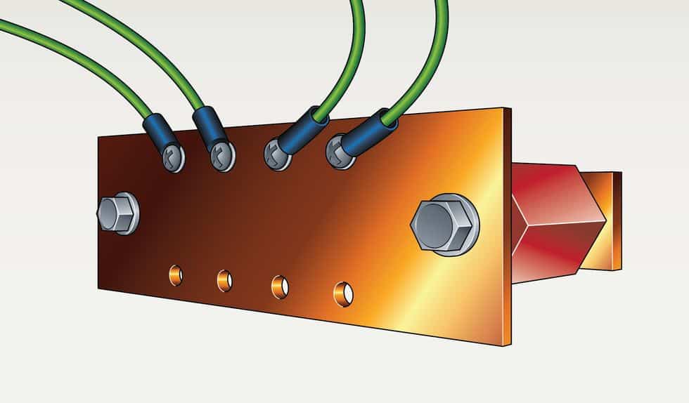
EARTH GROUND
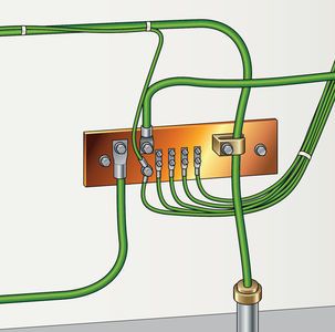
(BUS bar, building steel)
CAUTION: Only use electrical receptacles/outlets that have been previously tested using an approved circuit tester complying with CSA and/or UL standards.
NOTE: One copper grounding strap should be installed for every 1,000 square feet of ESD flooring. Each room should have a minimum of one connection to ground.
Installing a Ground Connection
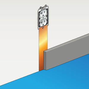
Method 1: Circuit Ground
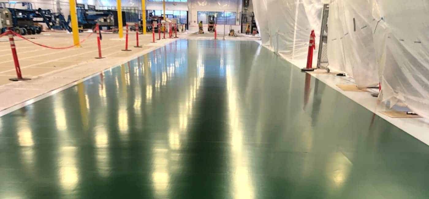
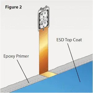
The ground connection should be installed after the primer has been applied and is dry to the touch—before applying the conductive topcoat (fig.1). When applied, the conductive topcoat will cover the grounding strap (fig. 2).
Required Materials:
- Screwdriver
- 24-inch copper grounding strap
- Conductive adhesive (not necessary if using peel-and-stick grounding tape)
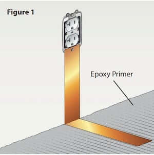
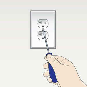
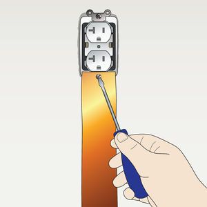
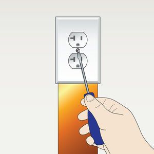
STEP 1: Remove the center screw on the cover of an AC electrical outlet using a screwdriver. Then, locate and remove the grounding screw inside of the outlet. This is most often found near the bottom of the receptacle.
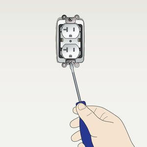
STEP 2: Punch a small hole in the 24” copper grounding strap. The hole should be smaller than the head of the screw removed in Step 1. Secure the copper strap to the AC electrical outlet with this screw and reattach the outlet cover.
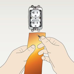
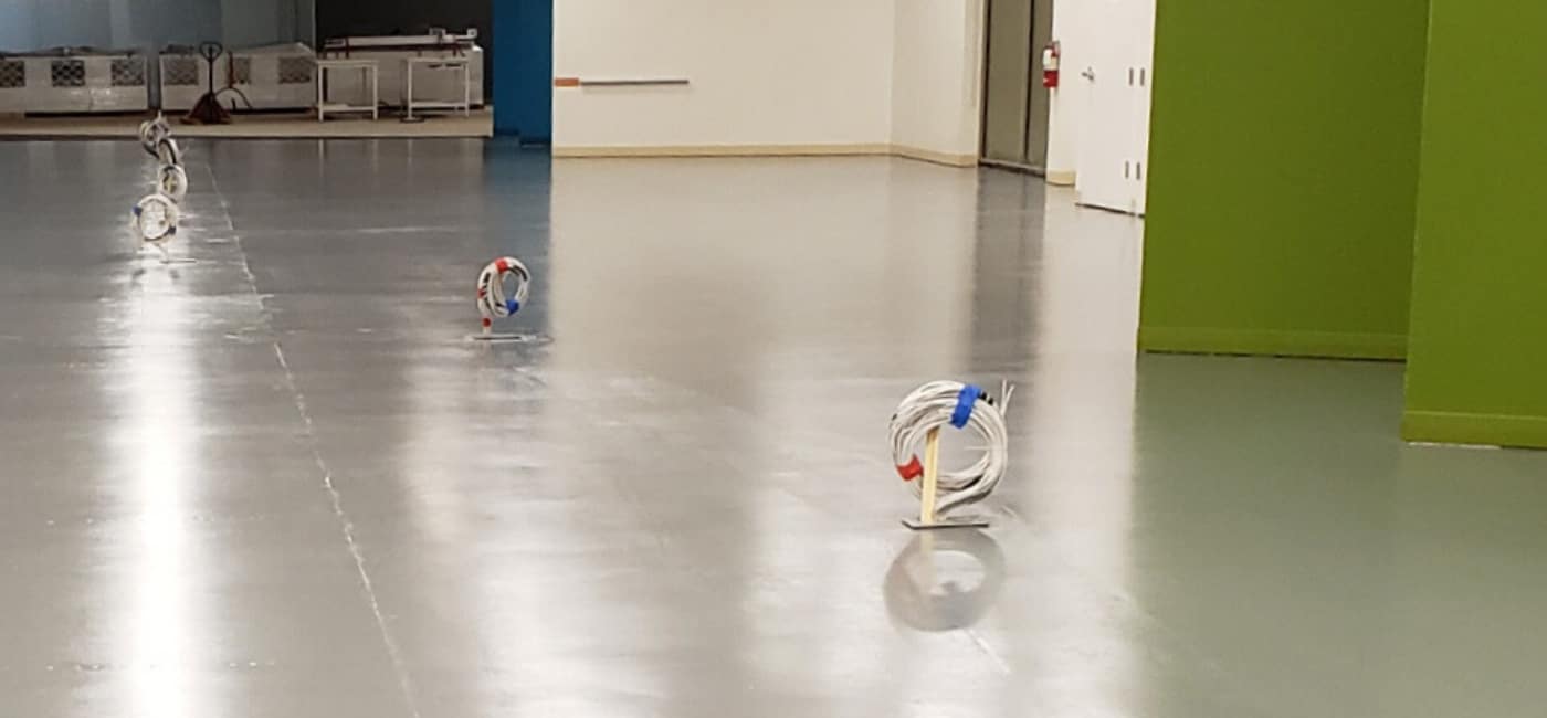
STEP 3: Affix the Copper Grounding Strap to the Floor
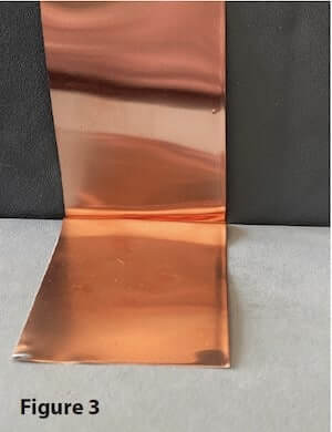
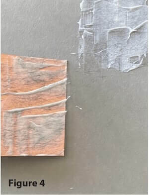
StaticWorx most often supplies a special adhesive-backed copper tape for grounding floor coating installations. Affix the grounding strap to the epoxy primer by removing the backing and exposing the factory-applied adhesive. Run the copper strip down the wall and lay it directly onto the floor, extending approximately 6 inches or more into the room. In most cases, this will create a 90-degree right angle perpendicular to the wall (fig. 3). When installing a non-adhesive grounding strap, a small amount of conductive adhesive shall be used to secure the copper strap in place (fig. 4 & 5).
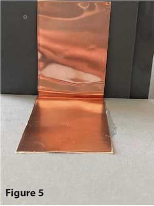
STEP 4: Install the conductive urethane topcoat material, coating over the copper strap on the floor (see coating installation instructions for details). For a cleaner looking installation, the copper strap should be covered by wall base after the coating has cured.
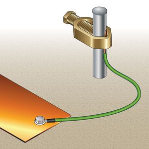
Method 2: Natural Earth Ground
If the floor will be installed on-grade or below grade, a copper grounding rod can be driven into the ground, creating an earth ground for the floor.
Required Materials:
- Ground Rod
- Grounding Clamp
- 24-inch copper grounding strap
- #10 or #12 gauge insulated copper wire (optional)
- Conductive adhesive (not necessary if using peel-and-stick grounding tape)
STEP 1: Drive the 4- to 6-foot rod into the ground until only 2 or 3 inches of the rod remains exposed. The floor coating shall then be installed per StaticWorx written instructions.
STEP 2: Affix the copper strip to the conductive floor coating using the self-adhesive copper grounding tape or a non-adhesive copper grounding strap, attaching with conductive adhesive, as described in Method #1. Leave approximately 10-12 inches of the copper strip exposed. This end of the grounding strap will be attached to the grounding rod.
STEP 3: Attach the copper grounding strap to the exposed end of the rod using a grounding clamp, usually sourced from the same manufacturer as the grounding rod (refer to www.stormgrounding.com). If necessary, a #10 or #12 wire can be attached to the grounding rod.
STEP 4: Run the wire from the rod to the grounding strap and tie it to the strap with a wire nut.
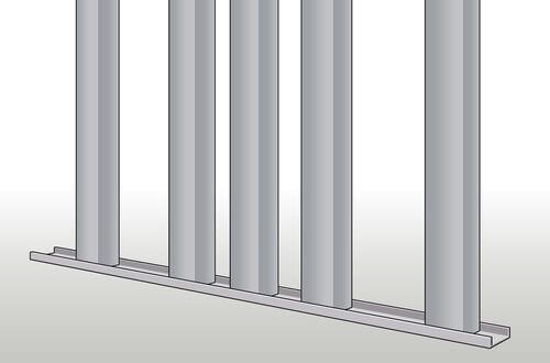
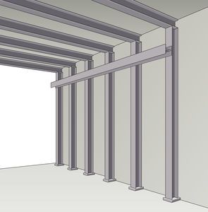
Method 3: Earth Ground
METHOD 3: EARTH GROUND If the building is constructed with exposed steel support columns, the copper grounding strap can be attached directly to one or more of the columns. The beams must be made of bare metal. Paints and coatings must be removed from beams prior to attaching copper straps. Alternatively, copper BUS bars can also serve as a dedicated Common Point ESD Flooring Ground Connection.
Required Materials:
- 24-inch copper grounding strap
- Power Drill
- Grounding screw or clamp
- Conductive adhesive (not necessary if using peel-and-stick grounding tape)
STEP 1: Affix the copper grounding strap or tape to the conductive floor coating as described in Method #2.
STEP 2: Drill a hole in the support column.
STEP 3: With a grounding screw or clamp, attach the end of the copper strap directly to the column. Mount a grounding clamp to the column and use it to clamp the copper strap. Copper grounding straps should be attached to aluminum studs using sheet metal screws and a washer.
STEP 4: A continuity test should be conducted with a volt ohm meter (VOM) to confirm a compliant electrical ground connection between the copper strap and electrical ground.